ASSEMBLY
In aviation and STEM fields, it is important to follow all steps in the correct order.
CAUTION - Screws should only be finger-tight. Do not hold the driver with a fist. Over-tightening can damage aircraft components.
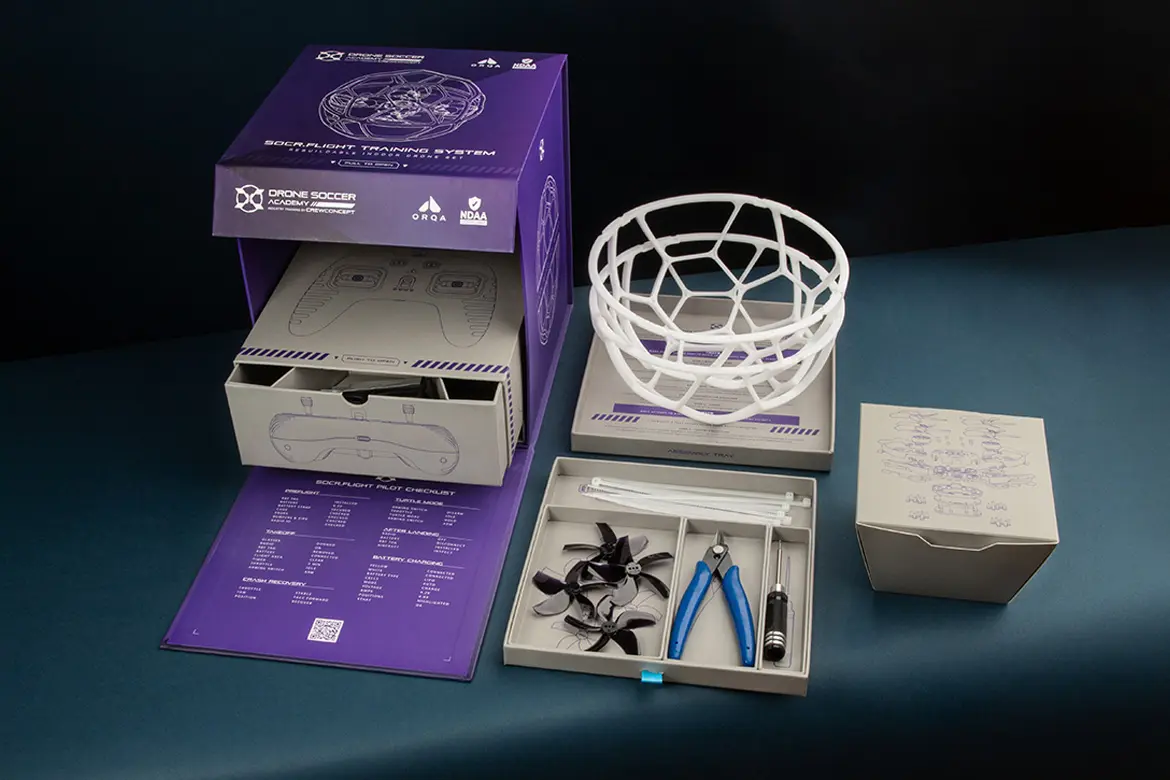
NOTE - Work over the Assembly Tray to avoid losing small parts on the floor. Steps and references are printed there.
STEP 1 - AIRFRAME
Open the STEP 1 BOX. Assemble according to AMM Chapter 20 STANDARD PRACTICES AIRFRAME, simplified below:
- Loop the Battery Strap (1) through the Carbon Fiber Plate (2) cutouts with the velcro on the outside, and rubber grip on the inside. Pull all the way through to the metal fastener.
- Apply adhesive Rubber Battery Pad (3) onto Carbon Fiber Plate on the same side as the Battery Strap fastener. Ensure holes are aligned.
- Align Lower Canopy (4) with the Electronics Board (5). Thread 8x Hex Screws (12mm) through the Carbon Fiber Plate and Lower Canopy. Secure with 8x Metal Standoffs on the far side of the Electronics Board.
- Align the upper canopy and secure with 4mm Hex Screws.
- Retrieve 4x Bumpers (7) and 12x Hex Locknuts. Orient the locknuts with the circular nylon side facing up, and press into the three corresponding Bumper indents on each.
- Place the bumper on top of each Electronics Board Arm and secure with 7mm Hex Screws from the bottom.
STEP 2 - BUMPERS
Open the STEP 2 Box. AMM Chapter 54 PYLONS (BUMPERS) simplified below:
- Press the lock nuts down into the indents on the bumper, with the flat metal side downward and the circular nylock side visible
- Place the bumper on the top side of the electronics board. Thread three 7mm screws through the bottom of the electronics board, and secure into the lock nuts.
STEP 3 - MOTORS
Locate 4x Motors (8) and 16x Hex Screws (7mm). Install by referring to Maintenance Manual (AMM) chapter 70 STANDARD PRACTICES MOTORS, simplified:
- Plug the motor into the Flight Controller, ensure the plug is flipped the correct way.
- Hole the motor in place on the bumper, cable facing inward, and secure with four 7mm screws from beneath the electronics board.
STEP 4 - PROPS
Install by referring to the Maintenance Manual (AMM) chapter 60 STANDARD PRACTICES PROPELLERS:
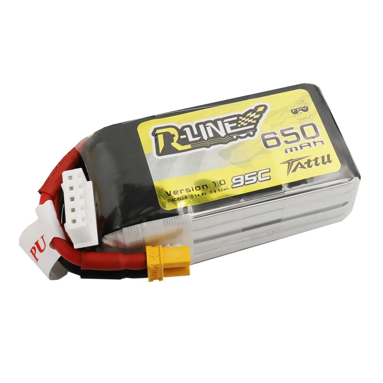
- Locate the yellow XT-30 power port which indicates the rear of the aircraft. The forward right propeller spins Clockwise (CW), select the correct CW propeller using references.
- Firmly press the propeller down onto the motor’s center post. Ensure the diagonal propeller matches this direction, then install the CCW propellers on the opposite motors.
- Insert two 7mm Hex Screws into the top of each propeller. To align the screw with the mounting holes, grip the motor bell with one hand and press down on the screws while rotating the propeller until they click into place. Tighten with the hex driver.
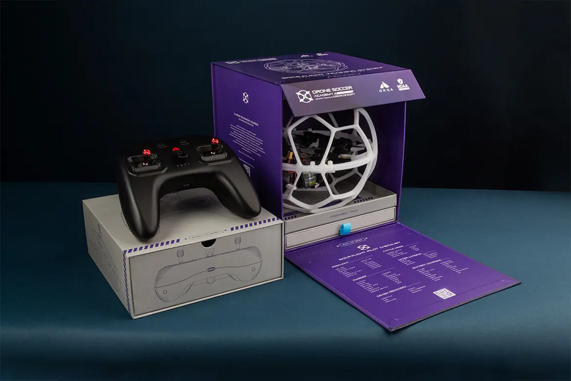
STEP 5 - CAGE
The top half is spherical, and the bottom half is truncated with a larger opening to access the battery. Find the direction indicator and ensure that both halves are aligned and fit snugly around the bumper cutouts:
- Secure with Zip Ties that pass around both halves, and through the bumper.
- Tighten the Zip Tie firmly with the square lock flush against the top or bottom so it does not protrude.
- Use the flush cutters to remove excess plastic length, cutting right against the lock to avoid any sharp points.